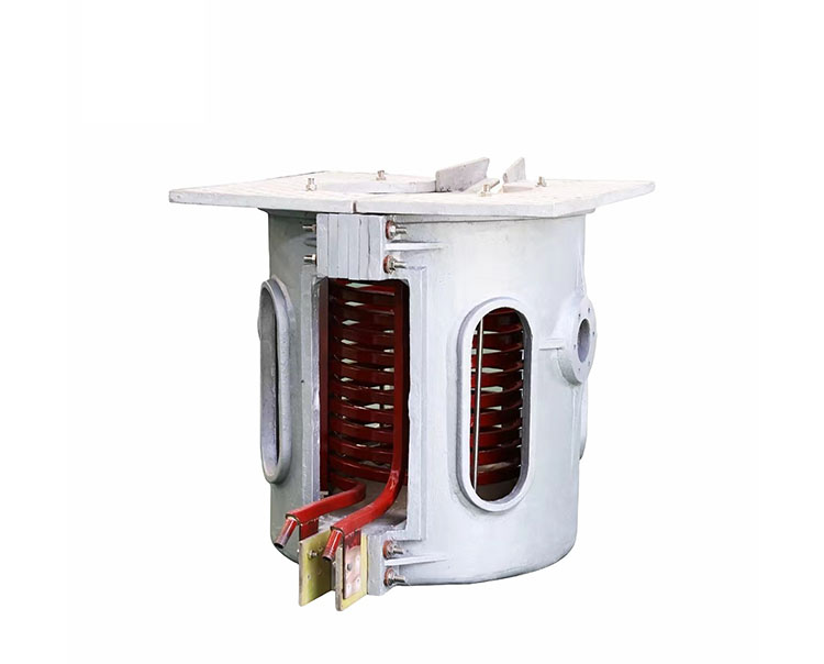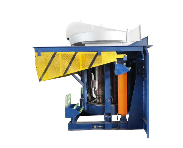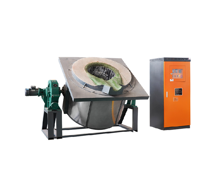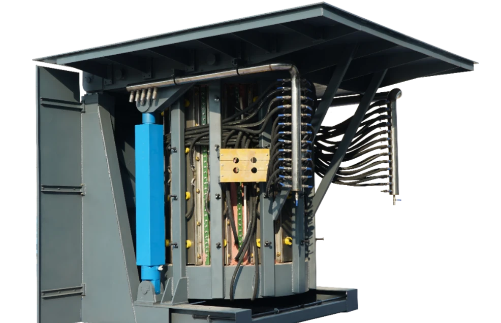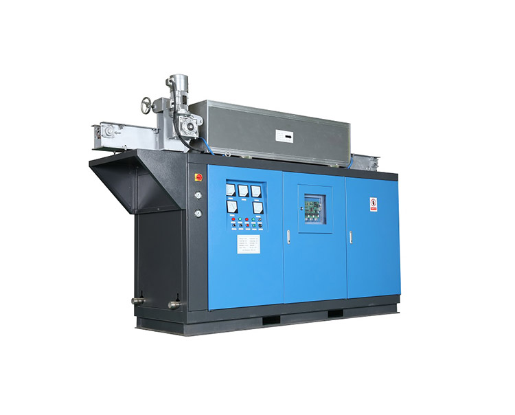
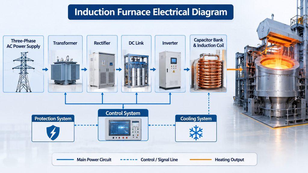
An induction furnace electrical diagram illustrates how electrical power is supplied, converted, controlled, and delivered to the induction coil during metal melting. It helps engineers understand the connections between the incoming power supply, transformer, rectifier, inverter, capacitor bank, and furnace body.
A typical medium-frequency induction melting system uses power electronic equipment to convert industrial AC power into the medium-frequency current required for induction heating. Understanding this electrical arrangement is important when installing, operating, maintaining, or upgrading industrial melting systems.
This guide explains the main electrical components, power circuit configuration, control systems, and protection functions commonly found in industrial induction furnaces.
1. Basic Induction Furnace Electrical Diagram
A medium-frequency induction furnace typically uses a multi-stage electrical conversion system. Its main purpose is to transform incoming three-phase AC power into controlled medium-frequency AC power for the induction coil.
A simplified electrical block diagram is shown below.
Basic Power Circuit:
Three-Phase AC Power Supply
           |
           v
Main Switchgear and Protection
           |
           v
Input Transformer
(When Required)
           |
           v
Rectifier (AC to DC)
           |
           v
DC Link and Filter/Choke
           |
           v
Inverter (DC to MF AC)
           |
           v
Resonant / Matching Circuit
(Capacitor Bank + Induction Coil)
           |
           v
Induction Heating of Metal Charge
The exact arrangement depends on the furnace design and power supply topology. Some systems integrate the transformer into the upstream plant electrical installation, while others use a dedicated furnace transformer.
The capacitor bank and induction coil also have different possible electrical configurations, including series-resonant and parallel-resonant arrangements.
This diagram represents the general power conversion process rather than a complete installation wiring drawing.
2. Main Electrical Components of an Induction Furnace
Each component performs a specific function in supplying and controlling the power required for metal melting.
2.1 Main Power Supply and Transformer
The electrical system receives power from the industrial three-phase supply network. Main switchgear, circuit breakers, and protective devices provide isolation and protection before power reaches the furnace converter.
A transformer may be installed to match the incoming electrical voltage with the requirements of the furnace power supply.
Its main functions include:
- Adjusting the supply voltage
- Providing the required electrical capacity
- Supporting the converter’s operating conditions
- Providing electrical isolation where required by the design
Transformer selection depends on the furnace power rating, incoming voltage, converter configuration, and site electrical infrastructure.
2.2 Rectifier
The rectifier converts incoming AC power into DC power for the inverter.
Depending on the power supply design, it may use diode or thyristor-based rectification.
The rectifier also influences the electrical characteristics of the incoming power. Multi-pulse rectifier configurations, such as 12-pulse or 24-pulse systems, may be used to reduce certain harmonic components when properly designed.
2.3 DC Link and Filter
The DC link connects the rectifier and inverter.
It provides an intermediate DC circuit that supports stable power conversion. Depending on the topology, this section may include:
- DC link capacitors
- Smoothing chokes or reactors
- Current and voltage sensors
- Protective components
The filter helps control electrical ripple and switching-related disturbances before power reaches the inverter.
2.4 Inverter
The inverter converts DC power into medium-frequency AC power.
It is one of the most important parts of the induction furnace electrical system because the output frequency and electrical characteristics must match the requirements of the induction coil and furnace.
Different inverter configurations may use SCR or IGBT power semiconductor devices.
The actual topology depends on the equipment design, power rating, operating frequency, and control requirements.
2.5 Capacitor Bank
The capacitor bank works together with the inductance of the furnace coil to form a resonant circuit.
The furnace coil has considerable inductive reactance. Capacitors are therefore incorporated to provide the required reactive compensation and establish the electrical conditions for efficient power transfer.
Capacitor bank configuration depends on whether the power supply uses a series-resonant or parallel-resonant circuit.
Its condition is important for stable furnace operation. Incorrect connections, damaged capacitors, or unsuitable capacitance can affect electrical performance and equipment reliability.
2.6 Induction Coil and Furnace Body
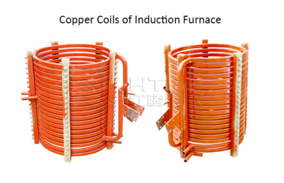
The induction coil is generally made from hollow copper tubing with circulating cooling water.
When medium-frequency current passes through the coil, it produces an alternating magnetic field. This field induces electrical currents in the conductive metal charge, generating heat through electrical resistance.
The furnace body contains the refractory lining and metal charge, while the coil and associated electrical components provide the heating function.
The electrical and mechanical arrangements must be coordinated to ensure reliable operation.
3. Power Circuit and Control Circuit: Key Differences
An induction furnace electrical diagram generally contains two major functional sections: the main power circuit and the control circuit.
Although they work together, their functions are different.
| Comparison | Main Power Circuit | Control Circuit |
|---|---|---|
| Main function | Transfers electrical power to the furnace | Controls and monitors system operation |
| Main components | Transformer, rectifier, inverter, capacitor bank, coil | Controller, sensors, relays, interfaces |
| Main signals | AC, DC, medium-frequency AC | Control and feedback signals |
| Primary concern | Power conversion and distribution | Regulation, monitoring, and protection |
Main Power Circuit
The power circuit carries the electrical energy required for induction heating.
Its components must be correctly matched according to furnace capacity, power requirements, operating frequency, and coil configuration.
The circuit also requires appropriate insulation, grounding, cable sizing, and protective devices.
Control Circuit
The control circuit coordinates the operation of the furnace power supply and supporting equipment.
It commonly monitors:
- Input voltage and current
- DC link conditions
- Inverter operating conditions
- Output power and frequency
- Cooling water temperature and pressure
- Water flow conditions
- Equipment fault signals
A control system may use a PLC, dedicated power electronics controller, or a combination of both.
The controller processes feedback signals and regulates the power conversion equipment according to the operating requirements.
4. Induction Furnace Cooling and Electrical Protection Systems
Cooling and protection systems are essential parts of a complete induction furnace installation, even though they are not all shown as components in the main power circuit.
4.1 Cooling System
The induction coil and power electronic components generate heat during operation.
A cooling system removes this heat to maintain suitable operating temperatures and protect sensitive electrical equipment.
Depending on the configuration, cooling arrangements may include:
- Closed-circuit cooling towers
- Water circulation pumps
- Heat exchangers
- Water distribution pipelines
- Temperature and pressure monitoring devices
The induction coil, power supply, and capacitor bank may have separate cooling branches or share parts of a cooling arrangement, depending on equipment design.
Cooling capacity and water flow must be determined according to the actual heat load and manufacturer’s specifications.
4.2 Electrical Protection
An induction furnace requires several protective functions to reduce the risk of electrical and equipment failures.
| Protection Function | Purpose |
|---|---|
| Overcurrent protection | Protects electrical components against excessive current |
| Overvoltage protection | Monitors abnormal voltage conditions |
| Undervoltage protection | Responds to insufficient supply voltage |
| Phase-loss protection | Detects abnormal three-phase supply conditions |
| Water-flow protection | Prevents operation under inadequate cooling conditions |
| Water-temperature protection | Monitors excessive cooling water temperature |
| Furnace leakage protection | Detects abnormal leakage through the furnace lining |
| Emergency stop | Allows the operator to initiate an emergency shutdown |
Protection arrangements vary according to the furnace model, power supply topology, and applicable electrical requirements.
These functions should be coordinated with the converter controller and the installation’s overall safety system.
For supporting components such as transformers, cooling equipment, and electrical cabinets, the induction furnace supporting equipment range should be considered as part of the complete system configuration.
5. How to Read an Induction Furnace Electrical Diagram
Reading an electrical diagram becomes easier when the power conversion process is followed in sequence.
The following approach helps engineers understand the main connections and identify the function of each section.
Step 1: Identify the Incoming Power Supply
Locate the three-phase input, main circuit breaker, isolation devices, and transformer. These components establish the incoming electrical supply.
Step 2: Locate the Rectifier
Identify the rectifier section and determine how incoming AC power is converted into DC power.
Step 3: Follow the DC Link
Trace the connections between the rectifier and inverter. Check the position of the smoothing choke, DC capacitors, and relevant monitoring devices.
Step 4: Identify the Inverter
Locate the power semiconductor switching section and examine how the DC link supplies the inverter.
Step 5: Check the Resonant Circuit
Identify the capacitor bank and induction coil connections. Confirm whether the circuit uses a series or parallel resonant configuration.
Step 6: Review the Control and Protection Circuits
Locate the controller, sensing devices, protective relays, cooling interlocks, and emergency stop connections.
This sequence provides a practical way to understand the overall electrical arrangement without confusing the main power path with auxiliary control wiring.
6. Common Problems When Interpreting Induction Furnace Electrical Diagrams
Several mistakes can lead to incorrect equipment installation, maintenance difficulties, or unsuitable system modifications.
Confusing Block Diagrams with Wiring Diagrams
A block diagram explains the functional relationship between major components, while a wiring diagram shows more detailed electrical connections.
They serve different purposes and should not be used interchangeably.
Ignoring Capacitor Bank Configuration
Series and parallel resonant systems have different circuit arrangements and operating characteristics.
The capacitor bank connections must follow the specific power supply design.
Overlooking Cooling Interlocks
The electrical diagram should identify the signals and protective conditions associated with cooling equipment.
Ignoring these connections may affect the reliability of the induction coil and power electronics.
Neglecting Grounding and Furnace Leakage Protection
Grounding, electrical insulation, and furnace leakage monitoring are important safety considerations.
They should be included in the installation design and verified by qualified electrical personnel.
Using an Incorrect Electrical Drawing
An electrical diagram from another furnace cannot automatically be applied to a different model.
Differences in power rating, converter topology, transformer arrangement, and resonant circuit configuration may result in incompatible connections.
7. Information Required for an Induction Furnace Electrical Design
Before preparing a complete electrical diagram, engineers should obtain the essential technical information about the furnace and installation site.
| Required Information | Why It Matters |
|---|---|
| Metal type | Determines melting requirements and furnace configuration |
| Furnace capacity | Helps establish power supply requirements |
| Required melting cycle | Influences power rating and operating conditions |
| Incoming supply voltage | Determines transformer and input configuration |
| Available electrical capacity | Confirms whether the plant supply can support operation |
| Power supply topology | Determines rectifier, inverter, and resonant circuit arrangements |
| Cooling conditions | Establishes cooling equipment and protection requirements |
| Installation layout | Determines cable routing, cabinet location, and equipment connections |
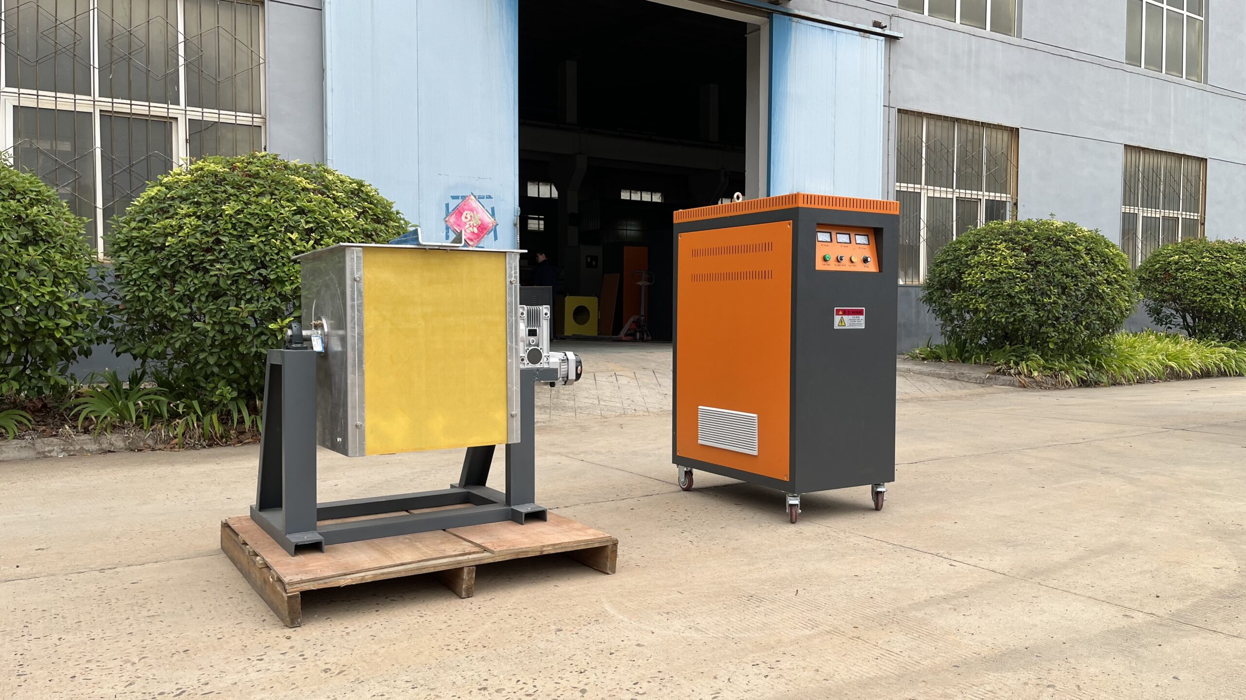
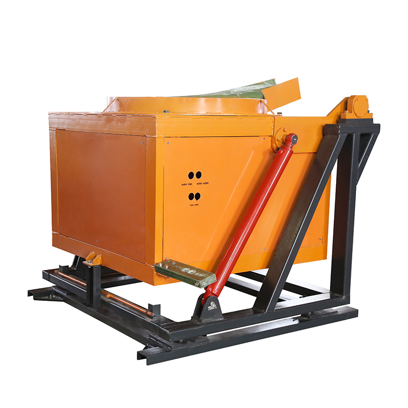
For example, a steel-shell melting furnace may use a configuration with a dedicated power cabinet, furnace body, transformer, and cooling system. The actual electrical arrangement must still be confirmed against the selected model and project requirements.
A steel-shell melting furnace is one example of equipment where the electrical system and supporting components must be evaluated together.
8. Frequently Asked Questions About Induction Furnace Electrical Diagrams
What does an induction furnace electrical diagram show?
It shows the main electrical components and their connections, including the incoming power supply, transformer, rectifier, DC link, inverter, capacitor bank, and induction coil. Detailed drawings may also include control wiring, sensors, and protection circuits.
What is the function of a rectifier in an induction furnace?
The rectifier converts incoming AC power into DC power, which is then supplied to the inverter for conversion into medium-frequency AC.
Why does an induction furnace use a capacitor bank?
The capacitor bank works with the induction coil to form a resonant circuit. It supports reactive power compensation and the electrical conditions required for stable power transfer.
What is the difference between a series and parallel resonant induction furnace?
The difference is mainly the electrical connection between the capacitor bank and induction coil. Series-resonant and parallel-resonant circuits have different voltage, current, and control characteristics. The appropriate arrangement depends on the converter design.
Why is cooling protection included in an electrical diagram?
The induction coil and power electronic components require adequate cooling. Monitoring water flow, pressure, and temperature helps prevent overheating and allows protective controls to respond to abnormal conditions.
Can one induction furnace electrical diagram be used for different furnace models?
Not necessarily. Different models may use different power ratings, rectifier configurations, inverter topologies, and capacitor bank arrangements. The electrical drawing must match the actual equipment configuration.
Conclusion
An induction furnace electrical diagram provides an essential overview of how electrical power is converted, controlled, and delivered to the furnace coil.
Understanding the rectifier, DC link, inverter, resonant circuit, control system, and protection devices helps engineers evaluate the complete melting installation and identify important technical requirements.
However, a simplified electrical diagram should only be used to understand system architecture. Actual installation and maintenance require model-specific wiring drawings, terminal diagrams, electrical specifications, and verification by qualified electrical personnel.
For a new melting project or an existing furnace upgrade, contact the technical team with the required furnace capacity, incoming supply conditions, metal type, and installation requirements to discuss the appropriate electrical system configuration.