Overview of Domestic Vacuum Induction Furnaces
Since China successfully trial-produced its first vacuum induction furnace in 1960, more than 20 years have passed. During this period, vacuum induction furnaces with capacities of 10 kg, 25 kg, 50 kg, 150 kg, 200 kg, 500 kg and 1,500 kg were successively designed and manufactured, forming an initial series of domestic vacuum induction furnaces.
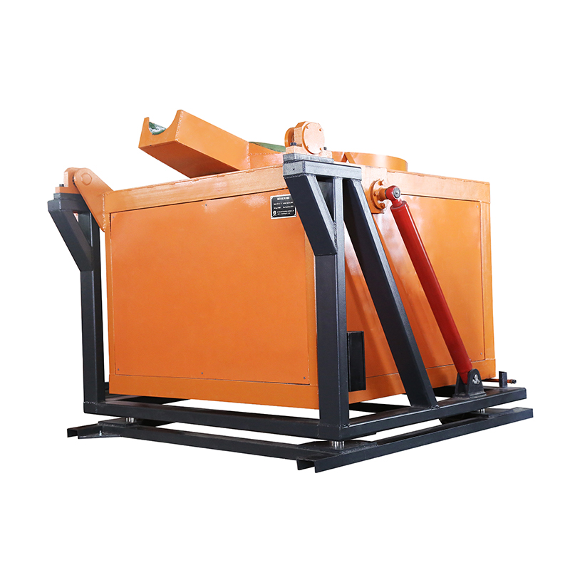
At present, the design, manufacturing and supporting systems for the power supply, vacuum system and furnace body have reached a considerable scale. This has laid a foundation for the future development of vacuum metallurgy equipment in China. The following is an overview of several vacuum induction furnaces independently designed in China.
ZG-0.05 Vacuum Induction Furnace
The ZG-0.05 vacuum induction furnace is a small furnace designed and manufactured by Jinzhou Electric Furnace Factory. Its appearance and structure are shown in Figure 2-45 and Figure 2-46.
The ZG-0.05 vacuum induction furnace is a horizontal intermittent-operation furnace. The crucible has a volume of 7 liters and can melt 50 kg of molten steel. It can be used to cast short steel ingots and long electrodes.
The power supply is a BPW50/2.5 medium-frequency generator set, which outputs medium-frequency current at 2,500 Hz and 380 V. The medium-frequency current is supplied to the inductor through coaxial rotating electrodes fixed on the furnace body. The total power of the power supply is 50 kW. This equipment can also use a medium-frequency thyristor static frequency converter as its power supply.
The capacitor bank connected in parallel with the inductor is equipped with 14 capacitors, model RYS-0.375-125/2.5, with a total reactive power of 1,750 kvar. The capacitor bank is divided into fixed capacitors and adjustable capacitors. According to the needs of the melting process, the number of connected capacitors can be adjusted at any time to ensure that the power factor cosφ is ±0.95.
Furnace Shell and Operating Structure
The fixed furnace shell and movable furnace shell are cooled by double-layer water jackets. The fixed furnace shell is supported on the seat-frame shaft. After loosening the fastening screws, it can rotate forward and backward to adjust the sealing surface.
The movable furnace shell is mounted on a trolley with wheels and can move along the track to open and close the furnace shell. There is an opening under the movable furnace shell for connection with the ingot cylinder when casting long electrodes. When casting short steel ingots, the opening is sealed with a round plate.
A ramming rod, temperature measuring rod and sampler are installed on the movable furnace shell. During melting, manual operation is used when ramming, sampling and temperature measurement are required. Three observation windows are arranged along the movable furnace shell for feeding, sampling, temperature measurement, ramming and pouring operations. The observation windows are equipped with a flash-frequency device to maintain a clear field of view.
Feeding System and Coaxial Rotating Electrode
A feeding system is installed on the fixed furnace shell. It includes a six-compartment feeding hopper, chute and vibration device, allowing various alloying elements to be added into the furnace during melting. The feeding system is operated through a combination of manual work and electric machinery.
The fixed furnace shell is also equipped with coaxial rotating electrodes. The outer end of the furnace is connected to the power supply through a current-collecting device, while the inner end is supported on a crucible bracket insulated from the furnace shell. The inductor is installed on this bracket.
To rotate the crucible, a sprocket and transmission device are installed at the outer end of the coaxial rotating electrode, and the crucible rotation is driven by a DC motor. The cooling water and power supply required by the inductor are both carried through the coaxial rotating electrode.
An exhaust port is arranged above the fixed furnace shell and is connected to the vacuum system through a short pipe.
Vacuum System of the ZG-0.05 Furnace
The vacuum system of the ZG-0.05 vacuum induction furnace consists of a three-stage pump group: a mechanical pump, a mechanical booster pump and an oil booster pump. The connection method is shown in Figure 2-47. The mechanical pump is 2X-7…
Note: The final pump model text is cut off in the provided image, so it is kept according to the visible content.