Structural Components and Mechanical Layout of Vacuum Induction Melting (VIM) Furnaces
A vacuum induction melting (VIM) furnace requires precise engineering to maintain stable, ultra-low pressure environments while handling high-temperature molten metal. The mechanical structure of the furnace body must balance vacuum seal integrity with operational accessibility.
1. The Furnace Shell (Vacuum Chamber)
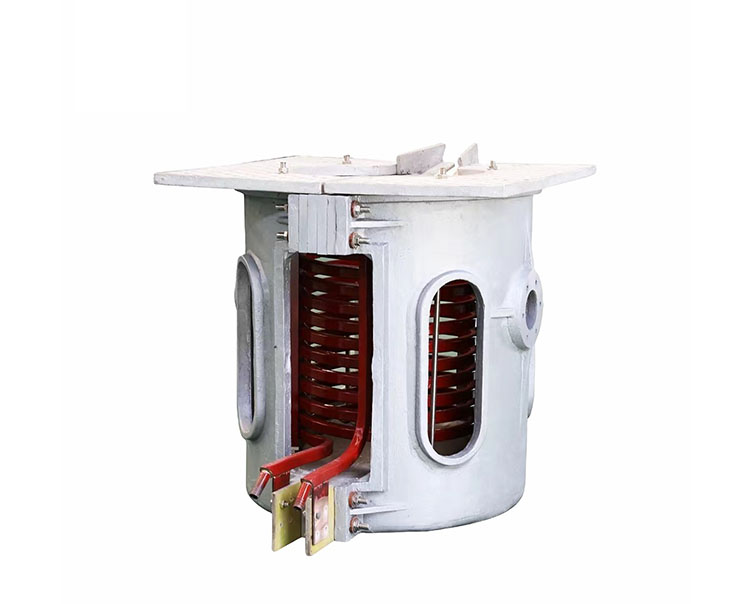
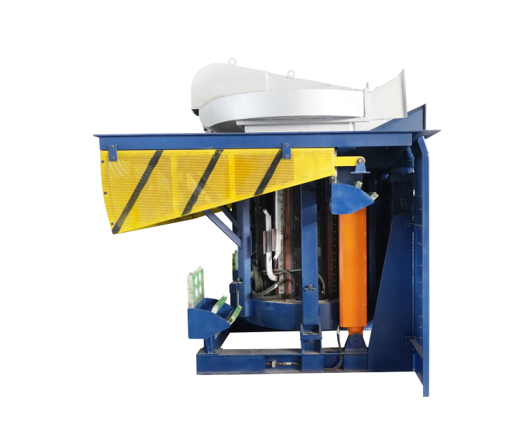
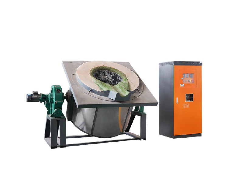
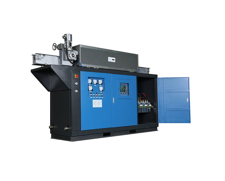
The vacuum chamber is the central structural component of a VIM furnace, enclosing the crucible, induction coils, and tilting mechanisms.
Structural Forms and Access Configurations
Industrial vacuum chambers are typically designed in either horizontal or vertical cylindrical shapes, depending on the furnace capacity and application:
- Small-Capacity Furnaces: Often utilize a vertical cylindrical shell with a flat or domed top lid. The lid can be swung or lifted away mechanically to provide full access to the internal components.
- Medium-to-Large Capacity Furnaces: Generally use a horizontal cylindrical shell with a domed front or rear door. The door is usually mounted on a heavy-duty hinge or a wheeled carriage track, allowing it to slide or swing open completely for easy loading, mold extraction, and crucible maintenance.
Material Specifications and Engineering
- Stainless Steel Construction: The vacuum shell is fabricated from high-grade austenitic stainless steel (such as 304 or 316). Stainless steel is selected because it is non-magnetic (preventing the outer shell from being heated by the induction coil’s stray magnetic fields) and offers excellent corrosion resistance under vacuum degasification conditions.
- Double-Walled Water Cooling: The entire shell features a double-walled construction creating an internal water jacket. High-velocity cooling water continuously circulates through this jacket to keep the outer metal skin at a safe temperature (typically below $50^\circ\text{C}$), protecting the vacuum seals from thermal degradation.
- Precision Flanges and O-Rings: All structural joints, viewports, and door interfaces utilize precision-machined flanges with trapezoidal or rectangular grooves. These grooves house high-elasticity Viton or silicone rubber O-rings to ensure a reliable hermetic seal against atmospheric leakage.
2. Charging Locks (Isolation Chambers)
To maximize thermal efficiency and protect the crucible from thermal shock, modern VIM furnaces operate on a semi-continuous cycle using advanced charging locks.
The Mechanism of Semi-Continuous Charging
A charging lock is an auxiliary vacuum chamber mounted directly on top of or adjacent to the main melting chamber. It is isolated from the main furnace by a heavy-duty, vacuum-sealed gate valve or isolation valve.
[Material Prepared] ➔ Lock Chamber Evacuated ➔ Isolation Valve Opens ➔ Charge Dropped into Crucible
- Isolation & Loading: While the primary crucible is actively melting metal under a deep vacuum, operators open the outer hatch of the charging lock (under atmospheric pressure) and load the next batch of raw material or alloying additions into a charging bucket.
- Pre-Evacuation: The outer hatch is sealed, and a auxiliary vacuum pump downscales the pressure inside the charging lock until it matches the internal pressure of the main melting chamber.
- Material Addition: Once the pressures are equalized, the internal isolation valve opens. A mechanical hoist or rams lower the charging bucket into the main chamber, dropping the material smoothly into the molten bath without breaking the core melting vacuum.
This design drastically reduces cycle times, eliminates the need to pump down the entire large chamber for every batch, and prevents air from interacting with hot refractory linings, thereby extending crucible lifespan.
3. Viewports and Accessory Systems
Safe Melt Monitoring
Because direct exposure to molten alloys under high thermal output can cause eye damage or cloud optical components, specialized viewports are integrated into the furnace shell:
- Strobe-Synchronized and Tinted Glass: Viewports use multi-layered, high-strength quartz glass with protective tinting to shield operators from intense infrared and ultraviolet radiation.
- Mechanical Shielding and Cleaning: Internal rotating metal shields or shutter plates protect the inner glass surface from metal vapor condensation during active degasification. Additionally, manual or motorized wiper blades allow operators to clear dust and slag particles from the internal viewing field without breaking vacuum.
Sampling and Temperature Measurement Locks
Similar to charging locks, smaller isolation ports are integrated for quality control:
- Immersion Thermocouples: Specialized vacuum-sealed lances allow operators to plunge dip-thermocouples into the liquid bath to capture real-time temperature profiles.
- Sampling Spoons: Mechanical sampling mechanisms can be lowered into the melt to extract a small liquid specimen, which is cooled and retrieved through the lock for chemical spectrographic analysis before tapping.
Summary of Core Component Design
| Component | Engineering Implementation | Primary Function |
| Main Vacuum Shell | Double-walled non-magnetic stainless steel with active water jacket. | Contains the vacuum environment; prevents stray induction heating. |
| Main Charging Lock | Dual-valve isolation pre-evacuation chamber. | Enables raw material addition without breaking the core processing vacuum. |
| Door Flanges | Precision machined with Viton or silicone O-ring profiles. | Eliminates atmospheric micro-leakage at major structural seams. |
| Viewports | Quartz glass with internal vapor shutters and wipers. | Allows safe, real-time visual inspection of the melt and slag profile. |
Conclusion
The structural design of a vacuum induction melting furnace balances heavy-duty mechanical strength with precision vacuum sealing. By utilizing non-magnetic stainless steel shells, active water-cooling loops, and robust charging locks, VIM systems provide the controlled, reliable environment necessary for high-yield, high-purity alloy production.