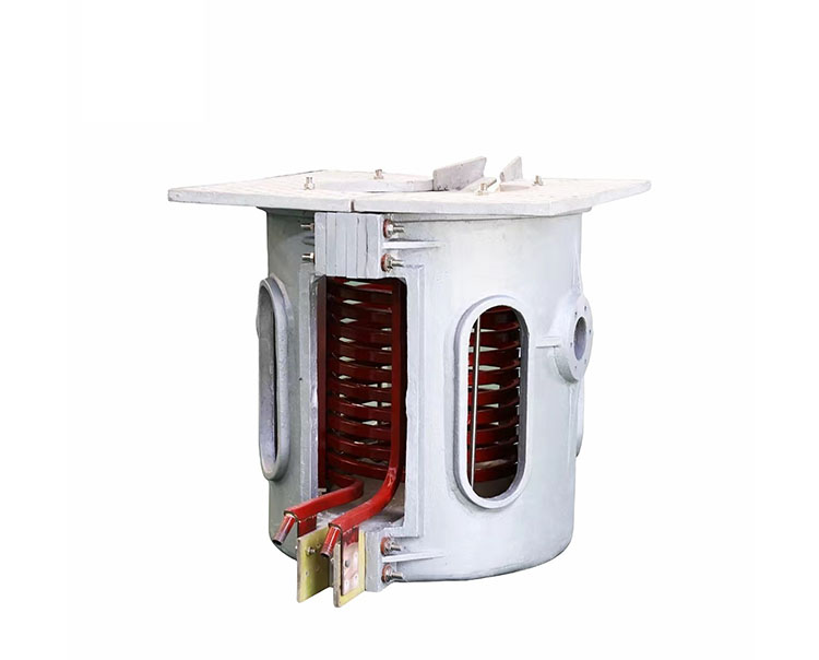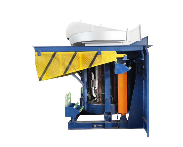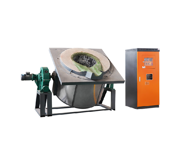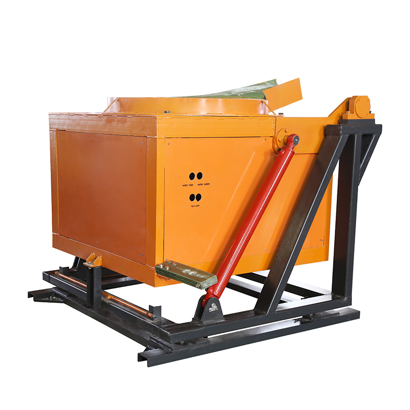
An induction furnace cooling system removes heat from the induction coil and other components that require cooling during operation. A properly designed system helps protect critical components, maintain stable operating conditions, and support reliable melting production.
An induction furnace water cooling system must match the furnace configuration, electrical power supply, operating duty, and cooling requirements of the individual components. Water flow, temperature, pressure, water quality, and heat-rejection capacity all influence system performance.
This guide explains how an induction furnace coil cooling system works, how to estimate its cooling duty, and what to consider when selecting a closed-circuit cooling tower.
Why Does an Induction Furnace Need a Cooling System?
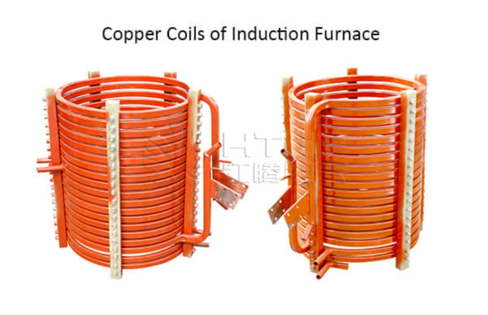
During induction melting, electrical current flows through the induction coil to generate the magnetic field required to heat the metal charge. Heat must also be removed from other water-cooled components where these are included in the equipment design.
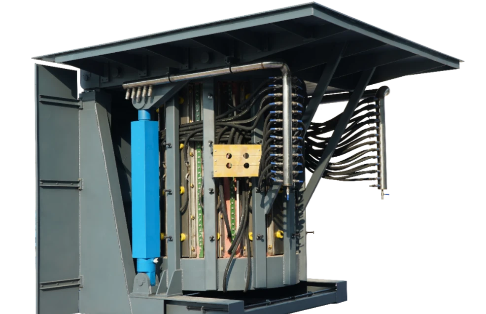
Depending on the furnace model, cooling may be required for the induction coil, power supply, capacitors, water-cooled connections, and other components. The exact circuit arrangement and cooling requirements vary by model.
Inadequate cooling can result in excessive component temperatures, protective alarms, or an unplanned shutdown. Restrictions, deposits, insufficient water flow, and inadequate heat rejection can all reduce cooling performance.
For this reason, the cooling system should be specified alongside the induction melting furnace equipment rather than selected independently after the furnace has been purchased.
Main Components of an Induction Furnace Water Cooling System
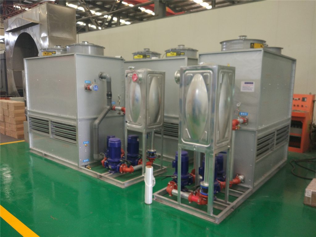
An induction furnace cooling system may include a closed-circuit cooling tower, circulation pumps, piping, valves, monitoring devices, and the cooling circuits serving the furnace and electrical equipment.
The precise arrangement depends on the equipment design. Some installations require separate cooling circuits for different components, even when they use the same heat-rejection equipment.
| Component | Main function | Key considerations |
|---|---|---|
| Induction coil cooling circuit | Removes heat generated in the coil | Required flow, water temperature, pressure, and coolant quality |
| Power supply and auxiliary cooling circuits | Cool electrical components where water cooling is required | Circuit-specific requirements and operating limits |
| Circulation pump | Maintains coolant circulation | Flow rate, pressure drop, pump duty, and reliability |
| Closed-circuit cooling tower | Transfers process heat to the surrounding environment | Heat-rejection capacity, ambient conditions, and water requirements |
| Piping, valves, and connections | Carry coolant through the system | Leakage, restrictions, material compatibility, and maintenance access |
| Monitoring and protection devices | Detect abnormal operating conditions | Temperature, pressure, flow where monitored, and equipment-specific alarms |
The induction furnace supporting equipment category lists a closed-circuit cooling tower and transformer. The final cooling arrangement should be confirmed against the specific furnace and its technical documentation.
Induction Furnace Coil Cooling System: What Matters Most?
The induction coil is a critical component of the melting furnace. Its cooling circuit must provide adequate heat removal throughout the intended operating cycle.
Water Flow Rate
The required water flow depends on the heat generated by the coil, the permitted water temperature rise, and the circuit’s hydraulic characteristics. A pump running normally does not necessarily mean that adequate flow reaches the coil.
Blocked passages, clogged filters, incorrectly positioned valves, or other restrictions can reduce actual flow. Flow requirements should therefore be obtained from the furnace manufacturer’s specifications rather than estimated from furnace tonnage alone.
Water Temperature
Both inlet and outlet water temperatures should be monitored where required. A rising outlet temperature or an unusual temperature difference can indicate increased heat load or reduced cooling performance.
The acceptable temperature range depends on the coil design and other water-cooled components. It should not be replaced by a generic industry value.
Water Pressure
Pressure must remain within the permitted limits of the coil, piping, hoses, and connected equipment. Excessive pressure does not automatically mean that cooling is better, because actual flow also depends on the complete circuit’s resistance and pump performance.
Unexpected pressure changes should be investigated alongside flow, pump operation, valve position, and possible leakage.
Water Quality
Water quality affects scaling, corrosion, and the risk of deposits forming inside cooling passages. The required treatment depends on the circuit materials and equipment specifications.
The closed-circuit cooling tower product page specifies softened water as the coolant. Appropriate water treatment and maintenance remain important to the performance of the complete cooling system.
Closed-Circuit Cooling Tower for Induction Furnaces
A closed-circuit cooling tower transfers heat from the circulating process fluid to the external environment through a heat-exchange surface. In a typical design, the process fluid flows inside the tubes, while an external spray-water and airflow arrangement helps remove heat. The two fluids remain separated by the heat-exchange surface.
This arrangement can help reduce direct contamination of the process fluid. Actual scaling and corrosion risks still depend on water treatment, materials, operating conditions, and maintenance.
The product page lists the following design features:
- Softened water used as the coolant.
- 304 stainless steel or red copper cooling tubes.
- A copper-core waterproof motor.
- A spray-water collection arrangement designed to collect water and mist and reduce circulating-water loss.
- A compact structure with convenient assembly and disassembly.
- Intelligent control and maintenance-oriented design.
These features are described on the product page. The page does not specify which tube material is supplied with each model, so the selected configuration should be confirmed when requesting a quotation.
The page also does not provide a complete set of rated cooling capacity, water flow, inlet and outlet temperatures, and operating pressure. These parameters must be verified against the selected model’s technical specifications.
A cooling tower should not be selected solely according to the furnace’s nominal melting capacity. Its heat-rejection capability must match the actual cooling duty and the site’s design conditions.
Cooling Considerations for Different Furnace Configurations
The required cooling arrangement depends on the furnace model and the way it operates. The published product information provides useful examples of why cooling requirements should be confirmed for the specific installation.
Aluminum Shell Melting Furnace
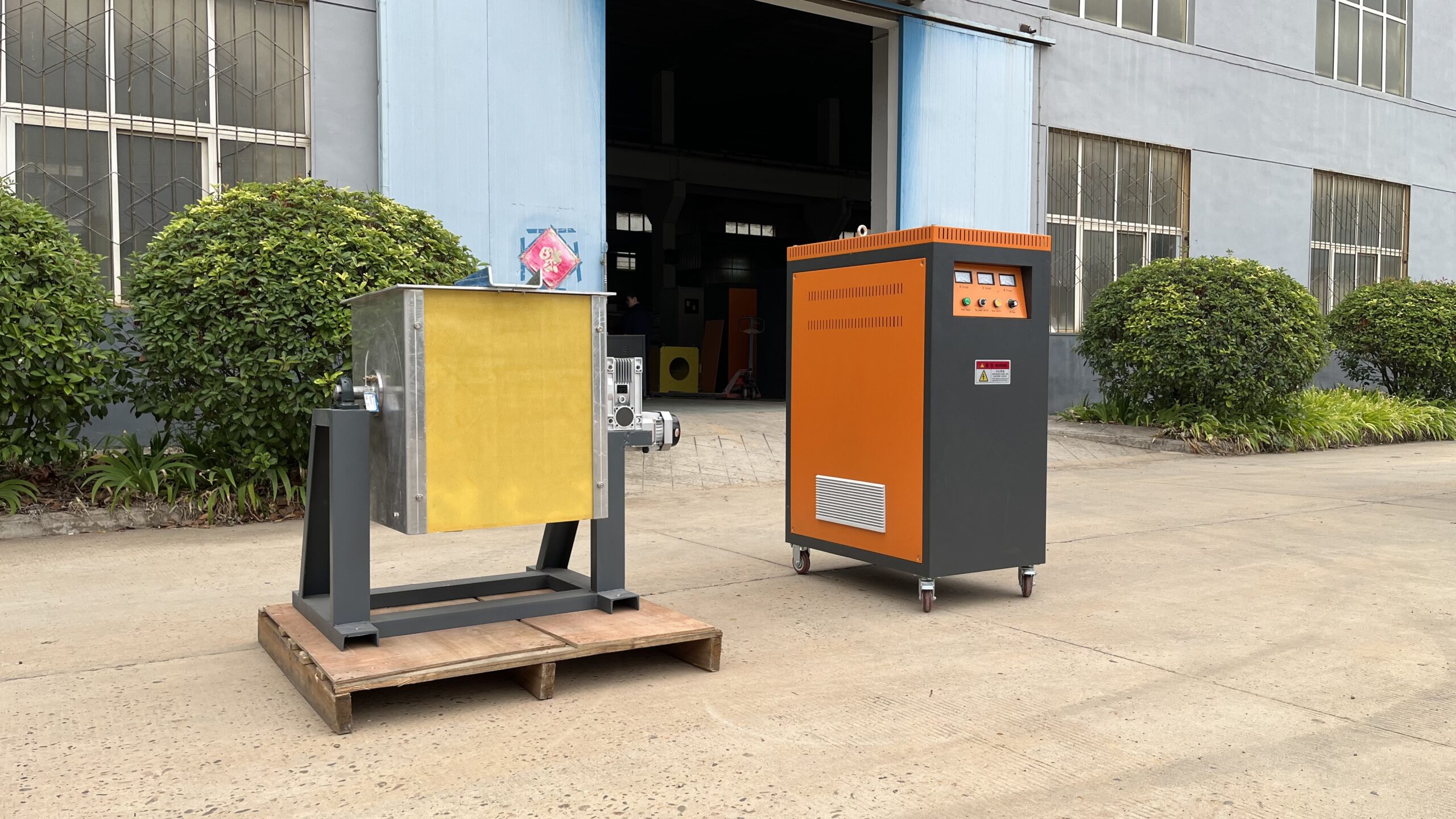
The aluminum shell melting furnace product page lists models with capacities from 0.1 to 20 tonnes and a melting time of 40–60 minutes per furnace. It also describes real-time monitoring of water temperature and pressure, together with overcurrent, overvoltage, and phase-loss detection.
The listed configuration includes a furnace-leakage alarm, a melting management system, and PLC control. The product page also identifies 304 stainless steel manifolds and clamps in the water-line arrangement.
These features show why cooling must be considered together with monitoring and furnace protection. However, the capacity range and melting time alone are not enough to determine cooling-tower size. The actual furnace power, cooling-circuit requirements, operating schedule, and heat load must also be considered.
Steel Shell Melting Furnace
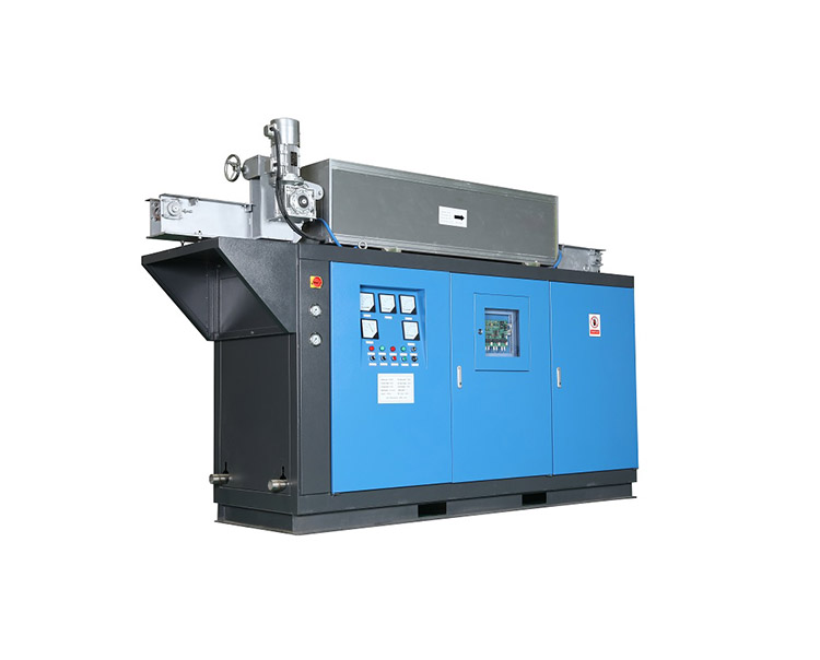
The steel shell melting furnace page describes a two-furnace arrangement powered by a single medium-frequency power supply, with flexible power allocation. Depending on the operating configuration, one furnace may be melting while the other is pouring or holding metal.
This operating arrangement makes it important to clarify the intended production schedule and power distribution between the furnace units.
Before sizing the cooling system, confirm whether the proposed operating modes involve one or both furnace loads, which components require water cooling, and how the cooling circuits are arranged. Do not assume that a two-furnace installation requires either twice the cooling capacity or the same cooling capacity as a single furnace without reviewing its actual design.
How to Estimate the Cooling Load
A basic heat balance can estimate the heat transferred to cooling water when the mass flow rate and water temperature rise are known.
The formula is:
[
\dot{Q}=\dot{m},c_p,\Delta T
]
Where:
- (\dot{Q}) = Heat transfer rate, in kW.
- (\dot{m}) = Water mass flow rate, in kg/s.
- (c_p) = Specific heat capacity of water, approximately 4.18 kJ/(kg·K) for a practical estimate.
- (\Delta T) = Water temperature rise, in °C or K.
For example, if the water mass flow rate is 1 kg/s and its temperature rises by 5°C:
[
\dot{Q}=1\times4.18\times5=20.9\text{ kW}
]
The water therefore carries approximately 20.9 kW of heat under these assumed conditions.
This is an illustrative heat-balance calculation, not a cooling-tower sizing result. The complete design must consider all relevant cooling loads, actual flow conditions, ambient wet-bulb temperature, required outlet temperature, and the characteristics of the selected tower.
For a real project, use measured operating data or the furnace manufacturer’s cooling requirements whenever available.
How to Select an Induction Furnace Cooling System
Before specifying a cooling system, buyers should prepare the following information.
| Selection factor | Information to confirm | Why it matters |
|---|---|---|
| Furnace configuration | Furnace model, rated power, and number of furnace units | Establishes the equipment and operating conditions to be cooled |
| Cooling duty | Heat load or supplier-defined cooling requirements for each circuit | Determines the required heat-rejection capacity |
| Water flow | Required flow for each cooling circuit | Influences pump selection and hydraulic performance |
| Operating temperatures | Required inlet and outlet water temperatures | Defines the intended cooling performance |
| Pressure requirements | Permitted operating pressure and circuit pressure drop | Helps confirm compatibility with the coil and connected equipment |
| Water quality | Required treatment, filtration, and material compatibility | Reduces the risk of deposits and corrosion |
| Site conditions | Ambient design conditions, available space, and utilities | Affects cooling-tower selection and installation |
| Operating schedule | Continuous operation, intermittent duty, and furnace sequencing | Helps establish the required cooling capacity under actual operating conditions |
Cooling-tower selection should be based on the specified operating duty rather than a generic capacity chart. Heat load, flow, inlet and outlet temperatures, ambient wet-bulb temperature, water quality, pressure drop, and available installation space are all relevant selection inputs.
Buyers should also confirm what is included in the equipment supply. A quotation for a closed-circuit cooling tower may not automatically include every pump, pipe, valve, sensor, electrical connection, or complete furnace cooling circuit.
Common Cooling Problems and Initial Checks
| Symptom | Possible causes | Initial checks |
|---|---|---|
| Water temperature rises abnormally | Increased heat load or inadequate heat rejection | Compare readings with specified operating limits and check tower operation |
| Low water flow | Pump problems, blocked filters, closed valves, or circuit restrictions | Check actual flow, pump status, filters, and valve positions |
| Pressure changes unexpectedly | Leakage, restrictions, or pump performance changes | Inspect pressure readings, connections, and circuit condition |
| Scale or deposits appear | Unsuitable water quality or treatment | Review water-treatment requirements and inspect affected components |
| Repeated cooling alarms | Abnormal operating conditions, sensor issues, or component faults | Record readings and follow the manufacturer’s troubleshooting procedure |
These checks can help narrow down possible causes but do not replace technical diagnosis. If water temperature, flow, or pressure falls outside specified limits, follow the equipment manufacturer’s operating and shutdown procedures. Protective interlocks should never be bypassed to keep a furnace running.
Cooling System Maintenance Checklist
Routine inspection helps identify deteriorating cooling performance before it interrupts production.
- Record water temperature, pressure, and flow readings where monitoring is provided.
- Inspect pumps, filters, valves, hoses, and connections according to the maintenance schedule.
- Check the cooling tower, spray-water collection arrangement, and heat-exchange surfaces as specified by the manufacturer.
- Review water treatment and inspect for deposits, corrosion, or leakage.
- Test alarms and protection functions according to the approved maintenance procedure.
- Compare current measurements with commissioning records and investigate significant deviations.
Inspection intervals should be based on the equipment instructions, water conditions, and actual operating duty.
Conclusion
An induction furnace cooling system must match the requirements of the induction coil, power supply, and other components that require cooling. Reliable performance depends on suitable water flow, temperature, pressure, water quality, heat-rejection capacity, and monitoring.
The closed-circuit cooling tower listed on our website uses softened water and includes design features intended to support heat transfer and reduce circulating-water loss. Its final selection, however, must be based on the actual furnace configuration and engineering requirements.
For equipment details, see our closed-circuit cooling tower and induction furnace supporting equipment.
To discuss a suitable configuration, contact our team with the furnace model, rated power, cooling requirements, operating schedule, and site conditions.