Traveling-Wave Induction Heating
Basic Concept of Traveling-Wave Induction Heating
Up to this point, all the applications previously described use single-phase induction coils. For higher-power applications, a three-phase power supply is usually used to achieve better load balance, although this is not a true three-phase system.
As already explained, if an induction coil is wound in several layers, the outer layer will inevitably heat the inner layer. Since the air gap between the outer layer and the workpiece increases, the power factor of the outer layer decreases. Although measures can be taken outside the induction coil to conduct the external magnetic flux, these methods cannot truly and effectively reduce the influence of the air gap.
To overcome these disadvantages, research has been carried out at Aston University in Birmingham according to a plan proposed by one of the authors. The aim is to make traveling-wave induction heating usable in many applications where pulsating magnetic fields are currently used. It is expected that this method will be applied more widely.
Principle Compared With a Three-Phase Motor
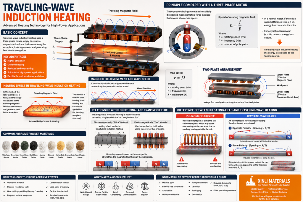
The basic principle of traveling-wave induction heating can be best understood by referring to a conventional three-phase motor. When the windings are placed in multiple slots and connected to a three-phase power supply, a sinusoidally distributed magnetomotive force is produced in space and moves at a certain speed.
Its speed can be determined by:
n = f / pWhere:
nis the rotating speed, in revolutions per secondfis the power supply frequency, in hertzpis the number of pole pairs
In a normal three-phase motor, a rotating component is arranged inside the stator, and this produces mechanical power. If there is a speed difference between the rotating magnetic field and the mechanical speed of the rotor, energy loss will occur in the rotor. For a synchronous motor, the slip s = 0, and there is no such energy loss in the rotor.
Because there is a speed difference, energy loss will always occur, and this appears as a reduction in motor efficiency.
Heating Effect in Traveling-Wave Induction Heating
In traveling-wave induction heating, the effect used is precisely the heating effect produced by this energy loss. If the rotor is fixed and made of metal, the lost energy will heat the rotor. In this case, the rotor can be regarded as the workpiece. This is the basic principle of traveling-wave induction heating.
This method has already been used for billet heating and blank heating, and it can also be applied in a flat form. In this form, its structure is more similar to that of a linear motor. A two-plate traveling-wave induction heater is one example of this structure.
Magnetic Field Movement and Wave Speed
In the air gap, a sinusoidally distributed magnetomotive force is formed in space and moves along the plane at a certain speed. The speed is:
v = fλWhere:
vis the moving speed, in meters per secondfis the frequencyλis the wavelength, in meters
In a two-plate arrangement, the upper and lower planes correspond to the effective magnetic flux and effective cross-sectional area. The leakage flux mainly returns along the ends of the steel plates.
Relationship With Longitudinal and Transverse Flux
It must be emphasized that the concept of traveling-wave induction heating is not necessarily related to “single-sided flux” or “longitudinal flux.” If the material is electromagnetically “thick,” the entire heating effect will be similar to that of longitudinal induction heating.
If the material is “thin,” traveling-wave induction heating can be applied on both sides of the workpiece by using the transverse-flux principle. The magnetic flux can also be strengthened by arranging opposing magnetic poles, allowing the flux to pass through the workpiece.
Difference Between Pulsating-Field and Traveling-Wave Heating
The main difference between a pulsating-field heater and a traveling-wave induction heater lies in the excitation effect.
In a pulsating-field heater, apart from leakage flux between the coil turns, the path of the induced current is essentially the same as the current path in the induction coil. Therefore, overheating at the two ends of the coil may occur due to auxiliary heating effects outside the coil.
In traveling-wave induction heating, an electromotive force is induced along the direction of wave travel. If adjacent magnetic poles form a complete magnetic flux circuit, several possible situations may occur:
- When the opposing magnetic poles maintain opposite polarity and the spacing is greater than
λ / 2, the induced current will close within the thin section of the workpiece. - When the opposing magnetic poles have the same polarity and the distance between them is close to
λ / 2, the induced current will also close along the side. - In the second case, if the plate is not thin, a mixed state of the two forms will occur. This depends on the ratio of the plate thickness to
λ / 2.